+ Reply to Thread
Page 6 of 11 FirstFirst ... 4 5 6 7 8 ... LastLast
Results 51 to 60 of 105

Thread: Roll rates in RCVD

  1. #51
    No Z, I obviously do not understand and with me all those engineers that worked in the 90s on the conceptual evaluation. Now try reading carefully these few words: "it did not work" and ask yourself which part of that phrase is not clear to you.

    Cheers,
    dynatune, www.dynatune-xl.com

  2. #52
    Senior Member
    Join Date
    Mar 2005
    Location
    Modena, Italy
    Posts
    363
    Quote Originally Posted by dynatune View Post
    Tim is correct with the interpretation of "lazy" but it was not the front causing this behavior, it was actually the retarded delay of building up of slip angle on the rear tires. Compare it to a step steer maneuver where on measured data one can see the "braking" free of the back end at the "famous" initial negative slip angle turning into positive and the small pike followed by drop off in the lateral acceleration followed again by the increase towards peak values.

    Yes indeed in the 90s there a lot of attempts to mimic the behavior of the active systems .... I was trying to explain that 3 pages ago, not with much success though - that all the interlinked systems were not all as good....

    Cheers,
    dynatune, www.dynatune-xl.com
    Interesting. So it seems the suspension may have been too front biased in terms of load transfer on turn-in. Were there any advantages in rear end stability on corner exit? Or were there problems there too?

  3. #53
    Quote Originally Posted by Tim.Wright View Post
    Interesting. So it seems the suspension may have been too front biased in terms of load transfer on turn-in. Were there any advantages in rear end stability on corner exit? Or were there problems there too?
    Those were definitely interesting times. I would not dare to say that the front suspension was too much front biased, there were issues with the tires, a tire war (and later especially when in 98 the grooved tires came other issues), there were issues with weight distribution and so on, the usual stuff. Beyond the linkage ideas and concepts we also started in those days in order to make the car "more" agressive in it's reactions to work with extreme rising rate rocker ratio's and also rebound stops to introduce drastic changes in wheel rates in extensions on one corner of the car to provoke transient diagonal load transfer effects. It did however make the "setup" of the car incredible complex.

    The good thing about the "active" cars was the engineers could give the driver a car that would exactly do what he wanted on a certain point on the track. Something like "if v= .. and SWA= .. and ay = ... then set left rear pushrod actuator = ... mm" and that "option" would only come into place once and not interfere with other parts of the track where a different setup was quicker.

    As I said before and I would use this as my final comment in this thread here: There is nothing wrong with aiming for a low "twist" stiffness and if executed with an active mechatronic system there will be advantages as history in the racing and OEM world has shown. If executed however purely with a passive analog mechanical system the racing and OEM world has found no "overall" benefit. Everyone can do what he or she likes with my 2 cent of information.

    Cheers
    dynatune, www.dynatune-xl.com

  4. #54
    Senior Member
    Join Date
    Mar 2005
    Location
    Modena, Italy
    Posts
    363
    I have been playing about with the longitudinal Z bars today to try and see in more detail what effects they have on the wheel loads under different conditions. I'm interested in this mainly because I am developing a car design for myself and wanted a deep understanding of the suspension's function. For anyone interested I have been posting my ramblings on my design here: Open Source Racecar

    While I still believe (at the moment) that for production cars a 2x ride springs and ARB is an acceptable compromise between packaging and ride quality - for a prototype or race car you could repackage or accept some complexity/weight penalty if there really is some performance to gain by running another system.

    Enter the Z bar...

    I have modelled a system with one ride spring per corner and 1 longitudinal Z bar per side linking the front and rear wheels. The Z bar has different lever arm lengths on the front and rear suspension connections to reach the desired roll stiffness distribution.

    I have put this into an analysis spreadsheet which I developed in my spare time. It takes a stiffness martix of the suspension as an input and calculates modal stiffness and responses of the body due to lat/long load transfer, warp inputs at the contact patch and single/dual wheel bump events. I started this spreadsheet over a year ago for the purpose of investigating interlinked suspensions.

    It models the chassis/suspension system basically like a 7 post rig. I.e. displacement inputs are given at the contact patches and the body is free to respond vertically and in roll and pitch. Additionally roll and pitch moments can be applied to represent lateral and longitudinal accelerations.

    I have modelled the Z bar suspension in this spreadsheet and compared them to:
    1. A traditional suspension system with springs/ARBs
    2. A mechanical interlinked system (all four wheel linked)

    All suspensions are matched for roll rate, roll distribution and where possible vertical stiffness and pitch stiffness.

    So in terms of responses to vertical loads at the CG here is the comparison:


    I have seen that with the Z bars I cannot acheive my desired vertical stiffness and spring centre (point where vertical forces give no pitch angle) simultaneously. This is because I set the bar stiffness to match the roll rate and roll stiffness as a first priority. The body mode shape plot on the bottom shows the vertical displacements of the front and rear axles with the CG shown as a circular marker and the spring centre marked with an X marker. The traditional system and the interlinked system have identical responses, and the Z bars have a very different response.

    After some algebra on the system equations, it seems that the vertical and roll responses are not independant like is the case in a traditional suspension. Worse still, the resulting vertical mode that I have got is almost twice as stiff as the traditional suspension and biased too far in front of the CG (23% of the wheelbase). This means it will pitch a lot due to vertical accelerations which is bad for ride (on a road car) and bad for aerodynamics (on a race car).

    Another disadvantage, particularly for a race car, is changing either the Z bar stiffness OR the springs results in changes to the ride AND roll AND pitch rates together. Nothing is independant so tuning at the track is going to require a calculator. Any desired roll distribution changes will require disassembly of the main ride springs which on a GT car is a significantly annoying thing to do.

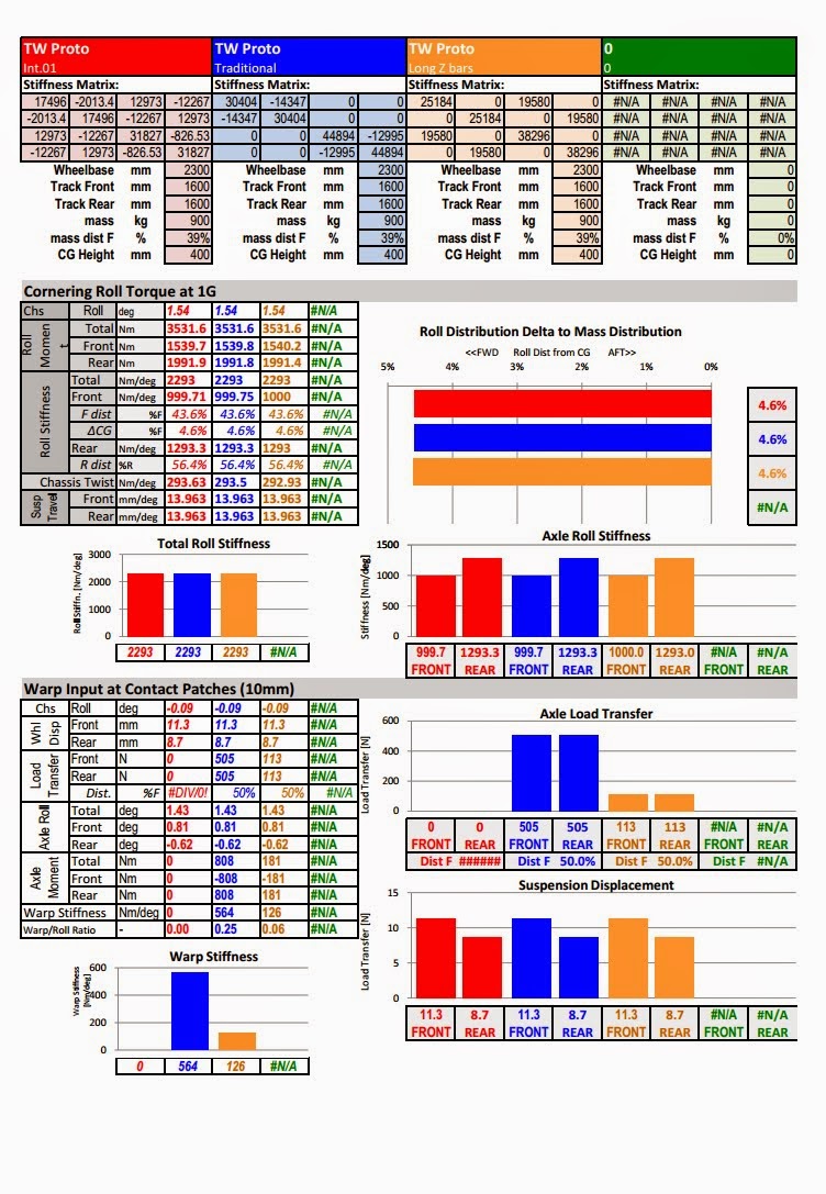
    Its not all bad for the Z bars though. There advantages lie in the low warp stiffness:


    You can see that I have tuned all 3 suspensions to have the same roll stiffness distribution and same total roll stiffness (top half of the page).

    On the bottom half we can see the response to a warp input at the contact patch. Here all three suspensions conform to the warp input identically in terms of the suspension travel, but the Z bar system and the interlinked system show significantly lower load transfers on the front and rear axles. Most of the load transfer on the Z bar suspension is due to the ride springs. This is an obvious advantage as the tyres will see less contact patch load variation due to road irregularities.

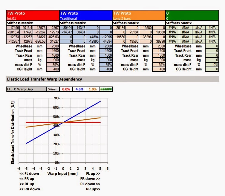
    After a discussion here a few weeks ago, I have also added an analysis on the sensitivity of the elastic load transfer distribution to a warp input. This confirms Erik's calc which show that very small warp inputs have a very large effect on the elastic load transfer distribution:


    Here we can see that the elastic load transfer distribution (ELLTD) changes by 4.6% PER MM of warp input at the contact patch. The Z bar suspension reduces this down to 1.0%. The interlinked suspension can basically eliminate it but this is at the cost of more parts and complexity.

    A few other points I found which are not shown above:
    1. I calculated energy dissipated by the body due to single wheel vertical inputs and saw no significant advantages of the interlinked system compared to the traditional system. In fact the interlinked suspension has the disadvantage that a vertical input at one wheel affects the loads on all of the wheels whereas on the traditional suspension only the other wheel on the same axle has a load imposed. When you then calculate the energy from the force and displacement required for the body to find its response equilibrium its the same for the traditional and interlinked system.
    2. The Z bar suspension is about half a stiff in pitch as the trditional system. This coupled with the large distance between the CG and the spring centre will likely result in pitch oscillations which will need to be managed. Then there is the problem of managing pitch angles under braking (critical in terms of aerodynamics) and squat under acceleration.

    So, after all that, I have to say my opinion remains unchanged regarding interlinked systems on road cars and race cars i.e. I think they are too complicated for serial production road cars and especially the Z bar solution which is reasonably simple but for me has too many critical disadvantages. For racecars, I think there are advantages to managing the warp mode better and in classes with open rules, I think you could have an advantage with an interlinked suspension, but I feel that Z bars are not the way to go.

    However, given that I am a moron, I may have overlooked something so I'm up for a discussion.


    Just a short disclamer: The design work on my own car (which includes this analysis) has been done outside of my work (in the cottage industry), so my findings and designs done there are more or less "open source" and I'm happy to discuss them. However any aspects which cross over with what I'm doing at work obviously I can't be so open about. So far I've done very little at work on ride, so most things are fair game for the moment but don't take offense if hold back on answering some things.

    Enjoy.

  5. #55
    Senior Member
    Join Date
    Mar 2005
    Location
    Modena, Italy
    Posts
    363
    Another reservation I had some time ago about soft warp suspensions is that without any stiffess or damping the warp mode is free to oscillate relatively uncontrolled on the tyres only which are famously underdamped. So I think there could be a good possibility of the wheel hop mode (approx 25Hz) being excited in a way which could kill grip or destroy ride quality depending on what your targets are.

  6. #56
    Senior Member
    Join Date
    Nov 2010
    Location
    NSW, Australia
    Posts
    352
    Tim,

    Thanks, that was excellent!
    Your comments regarding pitch are what I was trying to get my head around earlier (i.e. surely Z-bars would be 'pro-pitch' and therefore perhaps not suitable on an aero dependent platform).

    PS. I hope your car plays La Cucaracha on its many horns.
    Jay

    UoW FSAE '07-'09

  7. #57
    Senior Member
    Join Date
    Mar 2005
    Location
    Australia
    Posts
    1,690
    Tim,

    Thanks for sharing your numbers (yes, real numbers at last! ).
    ~o0o~

    I have only had time for a quick look at your linked blog of your project car. Just a few quick comments here (all "IMO"):

    * For all-round, easy-fast-driving (race or road) I would suggest stretching the wheelbase to ~2.6 metres. Keep F/R CG position and the Yaw-inertia similar to what you have (ie. passengers and engine centralised), but move front-wheels forward and rears backward a bit. This increases the Yaw-control-forces, while leaving inertial resitance low, so giving faster reaction to the driver's steer-inputs. Yaw-damping also increases, so less chance of suddenly "losing it".

    * Lower the CG by using a Subaru engine (easy 200+ hp, and dirt cheap). The shorter-wheelbase, higher-CG, rear-weight-biased cars, like the Lotus (and also most off-road buggies), suffer from lack of front-grip on corner exit. Essentially, a moderate amount of Accelerating-Gs can reduce your 39%F down to very little. This then requires a "point and squirt" driving style, where the car has to be pointing down the exit straight before power is applied. Lower CG means less load-transfer OFF the front-wheels for given Acc-Gs , = more predictable handling.

    * Reduce KPI to as small as possible (eg. 0 degrees, wrt wheel-camber). This easiest done with "large offset" wheels, but if you have to accept "Steering Offset" (= "scrub radius") of 20+ mm, then better than large KPI (IMO).

    * (Edit: And <700 kg total is a reasonable target (all steel, no CF!).)
    ~o0o~

    Back to your Z-bars post above. More details please!

    I suspect you are setting up a Z-bar "straw-man" so you can burn him down. Namely, you have added longitudinal-Z-bars to a four-corner-springs suspension (so 6 springs in total), when a 4 x Z-bar suspension would be a better comparison (2 x long, 2 x lat). Note that U-bars (eg. ARBs) can NOT carry Heave loads, so require other springs to do that. On the other hand, Z-bars can do that most important job of holding the car up, so no other springs required.

    Anyway, I will comment more on the details of your above post in a few days (work to do...). Meanwhile, can you clarify the contents of the "stiffness matrix" entries? And can you give the spring-rate details for the three different suspensions you are comparing (I suspect they are in the matrix, but...)? Oh, and also the details of the "4-wheel-fully-interconnected-suspension"?

    And, yes, that conventional suspension (4 x corner + 2 x ARB) sure does have a lot of load transfer PER MILLIMETRE of road induced warp-motion!

    Z

    (Edit: Jay, Longitudinal-Z-bars are NON-pitch. They don't control it at all (except through rising-rates, etc.). That is where lateral-Z-bars come in (ie. they control Heave and Pitch).)
    Last edited by Z; 04-07-2014 at 12:32 AM.

  8. #58
    Senior Member
    Join Date
    Mar 2005
    Location
    Modena, Italy
    Posts
    363
    Thanks for the commets on the project car... especially the comment on the weight is interesting. I've also been thinking about revisiting the mass distribution but this is another discussion.

    Quote Originally Posted by Z View Post
    I suspect you are setting up a Z-bar "straw-man" so you can burn him down. Namely, you have added longitudinal-Z-bars to a four-corner-springs suspension (so 6 springs in total), when a 4 x Z-bar suspension would be a better comparison (2 x long, 2 x lat). Note that U-bars (eg. ARBs) can NOT carry Heave loads, so require other springs to do that. On the other hand, Z-bars can do that most important job of holding the car up, so no other springs required.
    No straw man, like I said I've been researching this over the last year because I want to understand for ride/body control myself rather than relying on preaching from yourself, or anyone else about which system is the "best".

    I added 2 longitudinal Z bars to a conventional system (replacing the anti roll bar) because the conversation seemed to go in that direction a couple weeks ago. I will update the spreadsheet with 4x Z bars later this week when I have time.

    Quote Originally Posted by Z View Post
    Anyway, I will comment more on the details of your above post in a few days (work to do...). Meanwhile, can you clarify the contents of the "stiffness matrix" entries? And can you give the spring-rate details for the three different suspensions you are comparing (I suspect they are in the matrix, but...)? Oh, and also the details of the "4-wheel-fully-interconnected-suspension"?
    Very quickly the stiffness matrix is the stiffness coefficients (k01 - k16) for the system of equations;
    FZfl = k01xZfl + k02xZfr + k03xZrl + k04xZrr
    FZfr = k05xZfl + k06xZfr + k07xZrl + k08xZrr
    FZrl = k09xZfl + k10xZfr + k11xZrl + k12xZrr
    FZrr = k13xZfl + k14xZfr + k15xZrl + k16xZrr

    Where the body is fixed and vertical displacements are applied to the wheels. The suspension displacements and body movements are then solved in another matrix equation based on a freebody diagram of the chassis. I will detail all of this also later this week, right now the only documentation on this is in my head.

    The 4 wheel interconnected system I will also detail later but it started off as a purely mechanical system but I have changed parts of it to hydraulics because it became a packaging nightmare. It has 3 spring/damper units and can control pitch, roll and vertical stiffness' independantly. Which reminds me to ask you, how do you propose to implement damping on the 4xZ bar system?

    Quote Originally Posted by Z View Post
    (Edit: Jay, Longitudinal-Z-bars are NON-pitch. They don't control it at all (except through rising-rates, etc.). That is where lateral-Z-bars come in (ie. they control Heave and Pitch).)
    What Jay says has some sense to it. In that if you give a vertical input to the front axle (i.e. driving over a speed bump), the rear axle is forced away from the chassis (against the ground) and the reaction on the body lifts the rear up. This has the desired levelling effect of the body BUT at the cost of imposing a load variation on another wheel.

    Like I mentioned before, one disadvantage of all of these interconnected suspensions is that a force input on one wheel affects the loads on all the others. So I'm not so convinced that the control of contact patch load variation is going to be unconditionally better.

  9. #59
    Senior Member
    Join Date
    Mar 2005
    Location
    Australia
    Posts
    1,690
    Tim,

    I look forward to more details. Meanwhile, here are some general comments on your first big post above.
    ~o0o~

    ... - for a prototype or race car you could repackage or accept some complexity/weight penalty if there really is some performance to gain by running another [suspension] system.
    This issue of extra "complexity..." always amuses/annoys me (depending on my current mood).

    For the sake of all you students who may not be aware of this yet, the fact is that the vast majority of H. Sapiens will swear on their grandmother's grave that ANY NEW APPROACH, to doing ANYTHING, is ALWAYS far more complicated and expensive then "the way we have always done it...". This is regardless of any objective assessment of the matter.

    Numbers do not matter. Part-counts do not matter. Number-of minutes-to-make do not matter. Very often, NO ASSESSMENT AT ALL is made before the "new" approach is declared "far too complicated and expensive".

    Example 1. A proposed suspension that only uses 3 springs (or less!) is considered "too complicated". In contrast, current race suspensions that have 8 springs (4 x corner + 2 x ARB + 2 x "third-springs") are considered simpler. Go figure...

    Example 2. An unconventional Swing-Arm suspension, which requires one part, the "Arm", attached to chassis by 2 x BJs, is considered more complicated than the common Double-Wishbone+Toe-Link, which has four parts (upright + 2 x wishbones + toe-link), all attached to chassis by ~8 x BJs. Grooooaan...

    You students are, I guess, entitled to fool yourself with these irrational opinions. But I don't think it fair that you should try to fool your fellow students.
    ~o0o~

    I have seen that with the Z bars I cannot acheive my desired vertical stiffness and spring centre ...
    it seems that the vertical and roll responses are not independant ...
    Worse still, ...
    which is bad for ...
    Another disadvantage, ...
    Nothing is independant ...
    a significantly annoying thing ...
    All the above claims of "bad things happening" stem from a lack of understanding of Z-bars. Specifically, the bold section above is pretty much the DEFINITION of longitudinal-Z-bar behaviour! So, why the "it seems"?

    Longitudinal-Z-Bars couple Heave and Roll, but are independent of Pitch and Twist (with "non-linear" qualifications, as noted before). Lateral-Z-Bars couple Heave and Pitch, and are independent of Roll and Twist.

    By contrast, corner-springs couple Heave, Pitch, Roll, and Twist. So any suspension with these has NO INDEPENDENCE, whatsoever.

    And conversely again, a fully-interconnected-suspension has completely INDEPENDENT control of each of the all-wheel-modes (when appropriately defined). And it can be extremely simple.

    A Z-Bar suspension is somewhere in the middle of the above two. It connects two-wheels at a time, so can provide twice the "independence" of conventional suspensions, but only half the "independence" of fully-interconnected systems.

    Bottom line here, all of Tim's "bad things" can easily be resolved. Best way is to simplify the system (toss the corner-springs).
    ~o0o~

    Its not all bad for the Z bars though. There advantages lie in the low warp stiffness:
    ...
    Most of the load transfer [from warp input] on the Z bar suspension is due to the ride springs.
    ...
    the [conventional suspension] elastic load transfer distribution (ELLTD) changes by 4.6% PER MM of warp input at the contact patch. The Z bar suspension reduces this down to 1.0%. The interlinked suspension can basically eliminate it but this is at the cost of more parts and complexity.
    ALL of the "load transfer from warp input" comes from the ride (= corner) springs.

    Once again, note the prejudiced assumption that the "interlinked suspension" comes at a "cost of more parts and complexity". I stress again that this is an UNQUANTIFIED opinion (ie. no numbers) of someone who has just dipped their toes in the waters of interconnected-suspension, so really knows very little about them.
    ~o0o~

    In fact the interlinked suspension has the disadvantage that a vertical input at one wheel affects the loads on all of the wheels ...
    In fact, this is the great ADVANTAGE of interconnected-suspensions.

    A single-wheel-bump hitting a conventional suspension causes a large force to lift that corner of the car. As the car-body lifts, the wheel-loads on the other three wheels change. Typically, the two wheels closest to the one hitting the bump have their Fzs reduced, and the diagonally opposite wheel has its Fz increased.

    This is clearly seen when racecars clip the apex curb with their inner-front-wheel:
    If the car is front-heavy (say, tin-top), then inner-rear-wheel lifts completely off the ground, and outer-front has lesser Fz.
    If the car is rear-heavy (say, rear-mid-engined), then outer-front-wheel lifts completely off the ground, and inner-rear has lesser Fz.
    This is easily understood by considering the plan-view of the car, and CG position wrt the two lines that connect diagonally opposite wheelprints.

    A single-wheel-bump hitting an interconnected-suspension car has ALL FOUR wheels sharing the increased Fz forces that readjust the body position of the car. The amount of "sharing" is determined by the details of the interconnections, and can be varied arbitrarily (including so that it acts like a conventional suspension).

    Consider that a "fully-active" suspension is often considered the "ideal". Here, some sort of computer determines the share of the car's total Fz load that each wheel must carry, in any given situation. That is, all four wheels respond to any given event. An interconnected-suspension does effectively the same thing, but with the geometry of its interconnections acting as an analogue computer.

    Note, here, that a "change of program" for a mechanically-interconnected-suspension requires a change in the geometry of the linkage. However, there is no reason that this cannot be done whilst driving, say, in the same way that a brake-balance bar can be adjusted.
    ~o0o~
    ... will likely result in pitch oscillations which will need to be managed....
    ... the problem of managing pitch angles under braking ... and squat under acceleration.
    ... my opinion ... interlinked suspension ... too complicated ...
    ... Z bar solution ... too many critical disadvantages... not the way to go...
    Once again I stress that Tim has just dipped his toes in the waters. It seems that he is frightened that it might be too cold, or there might be all sorts of nasties swimming around down there, or something terrible is about to happen...
    ~o0o~

    However, I may have overlooked something so I'm up for a discussion.
    Well done, Tim! Very brave!

    Now, as I have pointed out countless times before, the vast majority of ground-vehicles use a soft Twist-mode. Lots of other people are doing it.....

    So, MAN-UP boy (!!!), and just bloody-well jump in!!!!!!!

    (Z mumbles... "Geeeez, what is it with these woosy-kids these days...".
    But, to be fair, Tim has been brave enough to dip his toes in... )

    Z

  10. #60
    Senior Member
    Join Date
    Mar 2005
    Location
    Australia
    Posts
    1,690
    More comments regarding posts subsequent to Tim's first big one:
    ~o0o~

    Another reservation I had some time ago about soft warp suspensions is that without any stiffess or damping the warp mode is free to oscillate ...
    ... good possibility of the wheel hop mode (approx 25Hz) being ...
    All suspension types, including single-wheel, two-wheel-interconnected, all-wheel-interconnected, +++, can be independently damped. The less the modal stiffness, the less damping required to suppress oscillation (from Critical-Damping ~ Sqrt(M.K)).
    ~o0o~

    No straw man, like I said I've been researching this over the last year because I want to understand for ride/body control myself rather than relying on preaching from yourself, or anyone else about which system is the "best".
    I agree 100% that you have the right approach. Just be careful that your own prejudices don't mislead you.
    ~o0o~

    Which reminds me to ask you, how do you propose to implement damping on the 4xZ bar system?
    Many ways are possible. Damper-in-parallel-with-spring-element is one way (damps only that mode). Someone recently posted an image from UQ showing such an implementation (though I think they are changing that...).

    However, as I have said many times before, (IMO) "dampers are crutches" that help a car with bad suspension get around faster. The analogy is with someone who has broken legs, and they can "run" faster with a crutch under each arm. However, with two healthy legs, the crutches just get in the way...

    Ultimately, the goal is to have springing that is clever enough that NO damping is needed. Damping, after all, is just friction that requires more fuel to be burnt, and thus slows the car down. A fully-active suspension does not, and should not, try to dissipate energy. Instead, it snubs out any oscillations by adjusting the Fz forces appropriately...

    The intermediate, and adequate, solution is simply to put just enough damping in to compensate for the not-quite-good-enough springing. Four corner-dampers, each of which damp all H/P/R/T modes, is more than enough. Just three corner-dampers, or maybe even just two, can do it, depending on details.

    (And please don't anyone say that "using two dampers is TOOOO complicated..."!)
    ~o0o~

    ... if you give a vertical input to the front axle (i.e. driving over a speed bump), the rear axle is forced away from the chassis (against the ground) and the reaction on the body lifts the rear up. This has the desired levelling effect of the body BUT at the cost of imposing a load variation on another wheel...
    "...at the cost of..."???

    Do the numbers! They are particularly easy in this side-view, "bicycle-model".

    In brief, the conventional suspension has two large Fz force spikes at the front and rear wheels (of the bike) as each passes over the bump. A soft-Pitch suspension has two much lower Fz spikes, felt, and SHARED, at BOTH WHEELS, as each passes over the bump. On the football paddock it is called "team-work". It wins games!

    This better bump-absorbency from soft-Pitch was the original motivation for Packard's adoption of Z-bars (the French also saw the soft-Twist advantages). Unfortunately, it is still not well explained in any of the VD textbooks that I have seen. And BTW, the issue of too much Pitch motion during Accel/Braking is best solved with highly non-linear Pitch-springing (falling-rate around centre of range, then rising-rate at ends of range).
    ~o0o~

    Enough for now...

    I look forward to more details.

    Z

+ Reply to Thread
Page 6 of 11 FirstFirst ... 4 5 6 7 8 ... LastLast

Posting Permissions

  • You may not post new threads
  • You may not post replies
  • You may not post attachments
  • You may not edit your posts