+ Reply to Thread
Page 27 of 31 FirstFirst ... 17 25 26 27 28 29 ... LastLast
Results 261 to 270 of 303

Thread: Suspension Design

  1. #261
    Senior Member
    Join Date
    Mar 2005
    Location
    Australia
    Posts
    1,690
    Back in 2005 I posted on this subject on the "Damper Histograms" thread. John Bucknell was kind enough back then to post on that thread some images that I sent him. I repost part of John's post here to show that nothing much has changed. (See also the current "Roll Rates in RCVD" thread for more of "nothing much has changed".)

    The deep lack of understanding of how these things work is evident in the images below that are taken from various VD/Suspension Design textbooks (and the notes I made when I first read them ). The lack of understanding of how to calculate modal-spring-rates is seen in the 2CV image. Tim's comments about how "it's just toooo haaaaard to package..." is seen to be utter nonsense from the BLMC images (the interconnecting hydraulic pipe is about the size of brake line). The lack of understanding of Z-bar ERMD is evident in the Olley book (compare with original Packard picture above).

    BTW, I had one of the BMC cars, and it rode well over bumps and cornered very flat. The "big-picture" engineering was very well done. However, the company went down the crapper, NOT because of the suspension, but because of pathetic detail design (similar to that seen in a lot of FSAE, especially English and Indian!), totally incompetent Top-Level management, and a lazy, unionised, and militant workforce.

    The following is cut-and-pasted from John's 2005 post:
    ~~~~~o0o~~~~~


    "Citroen 2CV and BMC, from "New Directions in Suspension Design", Colin Cambell, 1981 (with some comments by Z)


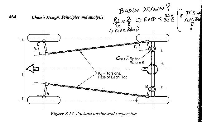
    Packard, from "Chassis Design...", based on notes by Maurice Olley, pre-1960? (with more comments...)


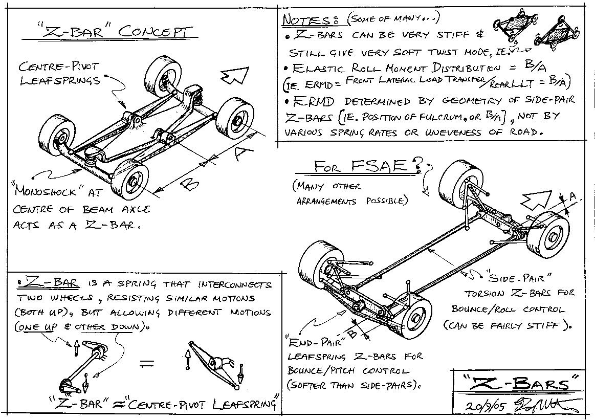
    Z-bar sketches by Z"

    Z

  2. #262
    Senior Member
    Join Date
    Mar 2005
    Location
    Modena, Italy
    Posts
    363
    Quote Originally Posted by Z View Post
    Tim's comments about how "it's just toooo haaaaard to package..." is seen to be utter nonsense from the BLMC images (the interconnecting hydraulic pipe is about the size of brake line). The lack of understanding of Z-bar ERMD is evident in the Olley book (compare with original Packard picture above).
    The images don't work for me (I think its because of my work firewall) but if you are introducing hydraulics, then yes the packaging is easy, but you have now significantly increased cost and complexity.

    So you either need a simple but bulky mechanical system, or a compact but complex (in relative terms) hydraulic system. Why is it nonsense that manufacturers don't want this added complexity?

  3. #263
    Tim, both are mechanical systems.

    The one marked for FSAE is packable albeit likely a bit on the heavy side. Might be a challenge to find a suitable torsion bar - motion ratio combination to achieve high stiffness, low weight and low compliance at the same time. But even if the system is on the heavy side at least everything is down low. Would love to see one of these in action.

    The other one might be on the bulky side but as we have seen there's imaginative ways to address packaging problems...
    "...when this baby hits 88 miles per hour... you're gonna see some serious shit" - Dr. Brown

  4. #264
    QU, Queensland Uni are designing their car for this year with cables interconecting front and rear suspension. Is this related to Z bars in any way?
    University of Tasmania (UTAS)

  5. #265
    Quote Originally Posted by Jonny Rochester View Post
    QU, Queensland Uni are designing their car for this year with cables interconecting front and rear suspension. Is this related to Z bars in any way?
    This sounded intriguing, so after some searching I found this on UQ's website (http://uqracing.com/):


    I don't know what their aims are with this system; but I would say this interconnection is related to the discussions on Z-bars, as the cables + front coilovers are working as Z-bars. There are a few other interesting elements on display there too.
    Nathan

    UNSW FSAE 07-09

  6. #266
    To comment a bit more on the UQ suspension:
    Spring-wise this is effectively a 3 Z-bar (2 longitudinal, 1 lateral) setup like those pictured in Z’s sketch above. The connecting cables combined with each front coilover act as the longitudinal Z-bars supporting heave and roll, while the rear coilover acts as the lateral Z-bar supporting heave and pitch.

    LLTD could be adjusted by using multiple pick-ups for the cable ends on the bellcranks to change the ratio of rear axle twist to front axle twist when the front springs remain the same length.

    There are only 3 dampers pictured, leaving the twist mode is undamped. The design clearly isn’t complete though, so this may change?
    Nathan

    UNSW FSAE 07-09

  7. #267
    Senior Member
    Join Date
    Mar 2005
    Location
    Australia
    Posts
    1,690
    Originally posted by Tim (page 26):
    The floor area of any modern car (road or race) is so absolutely full of stuff that there is nowhere to put these torsion bars.
    Originally posted by Tim (page 27):
    Why is it nonsense that manufacturers don't want this added complexity?
    (Note contradiction above...)

    Originally posted by Z on "Reasoning..." thread:
    * Don't argue with a fool. First they drag you down to their level, then they beat you with experience.
    Ah, those first "concept" meetings...
    ~~~o0o~~~

    Jonny, Nathan,

    Yes.

    Z

  8. #268
    Senior Member
    Join Date
    Nov 2010
    Location
    NSW, Australia
    Posts
    352
    It's possibly been answered before, but for the benefit of those unburdened with brilliance can someone explain how any of the discussed Z-bar suspensions would allow soft twist or individual wheel mode? Surely if you try to lift any individual wheel you have a Z-bar and a lateral leaf working against it (to use Z's "For FSAE" sketch above).

    Also: I understand how the longitudinal Z-bar would work at improving body control for a ride event (as shown under the "Moulton hydolastic suspension" image above), but in a pitch event surely the same bars would create essentially a pro-pitch situation, necessitating heavier ride springs (and exacerbating the twist/single wheel problem)?

    Lastly, assuming the cable in the UQ picture is infinitely stiff in tension, any roll event would have to be taken by the coil-overs anyway? This is a bit different to the Packard and Z systems, as they have rotatable torsion bars instead of rigid cables. They don't appear to have any lateral restraint, but as Nathan says it doesn't look finished...

    Kindly un-befuddle me...
    Jay

    UoW FSAE '07-'09

  9. #269
    Senior Member
    Join Date
    Mar 2005
    Location
    Australia
    Posts
    1,690
    Quote Originally Posted by Jay Lawrence View Post
    Kindly un-befuddle me...
    Jay,

    I think you can best be "fuddled" (or "re-fuddled"?) by looking at the little cars at the very top-right of the "Z-Bar" sketch. (As noted elsewhere, these are shown with 4 x Z-bars for clarity of the "twisting" motion, although only 3 are needed.) Anyway, the central diamond-shaped section represents the rigid chassis, and the four Z-bars form a rectangle connecting the four wheels.

    As long as there are flexible pivots between Z-bars and chassis, then the four wheels can move in Twist as shown (top-right). Single-wheel bumps are also possible. Note now that with "rigid" Z-bars and a single-wheel bump of 4 cm height, there will be 1 cm of Twist movement of the "suspension", and also 1 cm of chassis movement in each of Heave, Pitch, and Roll. (Oops, might have just "re-befuddled" you there...)

    I made a little model of this sort of stiff-Z-bar suspension back in the late 1990's, to help explain the concept to people. Geoff (BB) recently spent quite some time rolling this model back-and-forth over his finger, to see how it soaked up the "bump". Building a model like this is probably the best way to "fuddle" yourself on how it works.
    ~~~o0o~~~

    The "Moulton Hydrolastic suspension" is actually very cheap and simple (contrary to Tim's moaning ).

    The front-upper-wishbone and rear-trailing-arm are connected, at a MR = ~0.3 (or less?), to a pushrod that is rigidly fixed at its top to a shaped "piston" about 10 cm diameter (from memory?). This piston pushes against a rubber diaghragm similar to the "air-bags" commonly used on modern truck suspensions (so the diaphragm material is similar to a tyre sidewall). However, unlike the air-bags, above the Moulton diaphragm is a chamber filled with water + glycol (= antifreeze), hence "Hydro". The front and rear "Hydro" chambers are connected with a simple pipe.

    In the "Hydrolastic" version there is a thick rubber disc sealing off the top of the chamber. This deflects upwards, mostly by shear strain, to provide the springing. The later "Hydragas" versions have a heavy-duty rubber "balloon" in the top of the chamber (now capped with a steel dome), with the gas in the ballon providing the springing. Air (or nitrogen) pressure can be adjusted via a conventional tyre filling valve, but is at considerably higher than normal tyre pressures (I think about 10 bars, 150 psi??? Edit: ~10 bars unloaded, going up to ~20 bars with the car's static weight on the system).

    Importantly, both "Hydrolastic" and "Hydragas" springs have rising-rates in bump. In addition to this, the "piston" is also shaped to give a tunable rising-rate (from its increasing sectional area against the diaphragm). This gives what I earlier described as the "pendulum" springing. Namely, the rising-rates mean that no other springing AT ALL is needed to control Pitch. Put simply, when the car pitches forward the bump deflection of the front unit causes it to exert a greater force, and the rebound deflection of the rear unit causes it to exert a lesser force. Pitch problem solved!

    Lastly, why not just have interconnected air-bags, front and rear (the Hydragas without the "Hydra")? Well, the liquid-filled chamber of each suspension unit is divided horizontally by a steel plate. This has holes in it which are covered by shims and act as the damper valves. Liquid works better at damping than gas.

    Interestingly, because this "damper" is so large in diameter, the holes are quite large (large flows) and the shims are again made of rubber. Essentially, they are just largish rubber flaps covering the holes.

    Ah, yes Tim, ... "the cost and complexity"...!
    ~~~o0o~~~

    UQ's system has a stiff-cable in the middle, stiff-rockers at each end, a stiff-link at one end, and a squashy-link at the other. Packard's system has stiff-links at each end, stiff-rockers (lever-arms) at each end, and a squishy-torsion-bar in the middle.

    They might be different physically, but functionally they are the same (well, similar).

    Z
    Last edited by Z; 03-27-2014 at 02:42 AM.

  10. #270
    Senior Member
    Join Date
    Mar 2005
    Location
    Australia
    Posts
    1,690
    I recently received this PM asking about "Roll Stiffness". I will give my opinions here in case there are other students out there with similar questions. (I leave the OPs name and school anonymous in case they wanted it kept private.)

    Hello Z,

    I am from ... University in ... USA. I have been struggling with a concept that I believe is very simple, but I cannot find the answer online or in any of my books, I am likely looking in the wrong place because I am ashamed that I do not know. Never the less. Why do we want "some" roll in a race car. As in why do I not want to put my roll center on top of the COG and completely eliminate roll. Or above the COG and make the body "lean into the turn" I know roll bars are used to tune the roll stiffness, what happens when you go to stiff.

    My two theories is:

    1. Roll allows the dynamic camber gain to take effect
    2. If the roll stiffness is too high the suspension is not really working well to isolate bumps.

    I don't like either one of these, so I am looking for reason number 3.

    Appreciate any help you can give, even if it is just a point in the right direction of where to look. Like I said, I am ashamed I cannot find the answer on my own, but I have spent about 6 hours searching for something I think should be obvious.

    (Signed...)
    "... why do I not want to put my roll center on top of the COG and completely eliminate roll. Or above the COG and make the body "lean into the turn"..."

    Well, if you have independent suspension and a RC at CG height, then you can have quite significant jacking problems, which can be quite bad... You can cure this with stiff Anti-Axle-Heave springs as mentioned on the Swing-Axle sketch and post, quite a few pages ago. But the fact that the "suspension" is effectively rigid in the direction from wheelprint to CG means that you can get the "bouncing on tyres" problems listed in the last section below.

    A beam-axle with RC at CG height would behave a bit better, especially if it had a small amount of softish Axle-Bounce and Axle-Roll springing. But, generally, high RCs on beam-axles are NOT good on rough roads, because single-wheel-bumps act through the RC to "kick" the body sideways. The equal and opposite lateral force acting at the wheelprint then makes the tyre lose grip of the road.

    But on the smooth FSAE tracks you could get away with this.
    ~~~o0o~~~

    "1. Roll allows dynamic camber gain to take effect."

    Camber "gain" (aka camber "recovery", or "compensation"...) is really only a half-baked attempt to keep the wheels at an OK-ish inclination angle during cornering. Most independent suspensions (wishbone, strut, etc.) on most cars have well UNDER 100% "camber recovery". This means they LOSE camber during cornering (ie. the body-roll causes the wheels to adopt bad-ish camber angles). If they had no body-roll, then no camber loss at all (except for tyre squash), so better.

    Some suspensions have more than 100% camber recovery, so their wheels actually lean slightly into corners as a result of their body rolling outwards. This makes body-roll advantageous in corners, but these suspensions are in the minority (eg. pre-WW II Mercedes GP De-Dion rear suspension, some modern USA oval-track front suspensions, ...). But there can also be significant disadvantages here in other situations (ie. excessive camber change during heave and pitch motions, and large gyroscopic forces over bumps (though not on the Merc De-Dion )).

    The "Swing-Axle" and "Swing-Arm" suspensions that I sketched a few pages ago have 100% camber gain, so have NO camber loss during cornering. Importantly, this is regardless of the amount of body-roll, from completely roll-stiff, to lots of body-roll. There is camber change from pitch motions (eg. during accelerating or braking), but there are less of these on an FSAE track than roll in corners, so overall this sort of suspension is suited to FSAE.

    Bottom line here, you do not NEED body-roll to have your wheels at a good camber angle. And, for most independent suspensions, body-roll worsens the camber angles.
    ~~~o0o~~~

    "2. If the roll stiffness is too high the suspension is not really working well to isolate bumps."

    This is probably the most correct reason. But this is not too important in FSAE because the tracks are so smooth. However, it is certainly one of the main reasons not to have too much roll stiffness in a conventionally suspended road car (or sports car, or "Targa" racecar, etc.).

    And, as covered at length above , excessive roll stiffness of conventional suspensions completely stuffs your handling balance on anything but a near perfectly flat road. Put simply, the more stiffness in your springing (corner and ARB), the greater the variation in your LLTD when on "real" roads (= NOT perfectly flat).
    ~~~o0o~~~

    "I don't like either one of these, so I am looking for reason number 3."

    Another good reason for softening a suspension is to suppress "bouncing on the tyres". Cars with effectively rigid suspensions, as have won FSAE in the past (it is a historical fact, Pat), can develop a sideways stick-slip-stick... of their tyres during cornering, which then becomes a bouncing motion of the car on its outer tyres. This bouncing causes a massive reduction in cornering capability. And, importantly, this can happen on a perfectly SMOOTH AND FLAT road.

    A small amount of suspension movement is all that is needed to snub out this behaviour. About +/- 5 mm is all an FSAE-sized car needs (+/- 10 mm at most). Having a low spring-rate for this movement means that the damper forces can also be quite low. This type of behaviour is worst when running medium to high tyre pressures. Low tyre pressures, and the internal damping of racing tyres, can sometimes provide enough "suspension" to snub out this bouncing.

    Z
    Last edited by Z; 03-27-2014 at 01:34 AM.

+ Reply to Thread
Page 27 of 31 FirstFirst ... 17 25 26 27 28 29 ... LastLast

Posting Permissions

  • You may not post new threads
  • You may not post replies
  • You may not post attachments
  • You may not edit your posts