

Z - Single wheel bump would be a fairly major road anomaly (pothole) I suppose or a kerb, neither of which exist in FSAE.
In other terms, I think the idea of having major design work only starting in December is far too ambitious, you assume people are like robots and will work on concepts day in day out and lets be honest people are just lazy and wont do that!
One thing I did read which leaves me at somewhat of an issue is that RCVD says that the RC isn't completely linked to the kinematic and elastic weight transfer distribution in the case of a beam axle, in which case how does one determine the split and its relationship to the linkages used?
With regards to tips on the braking system, It's fair to say it's most likely going to be me spec'ing everything about them, our calipers are fixed as the current AP Racing 4 pots (too expensive to change) (also thanks BCU for lending them to us!) but master cylinder sizing, etc is up in the air.
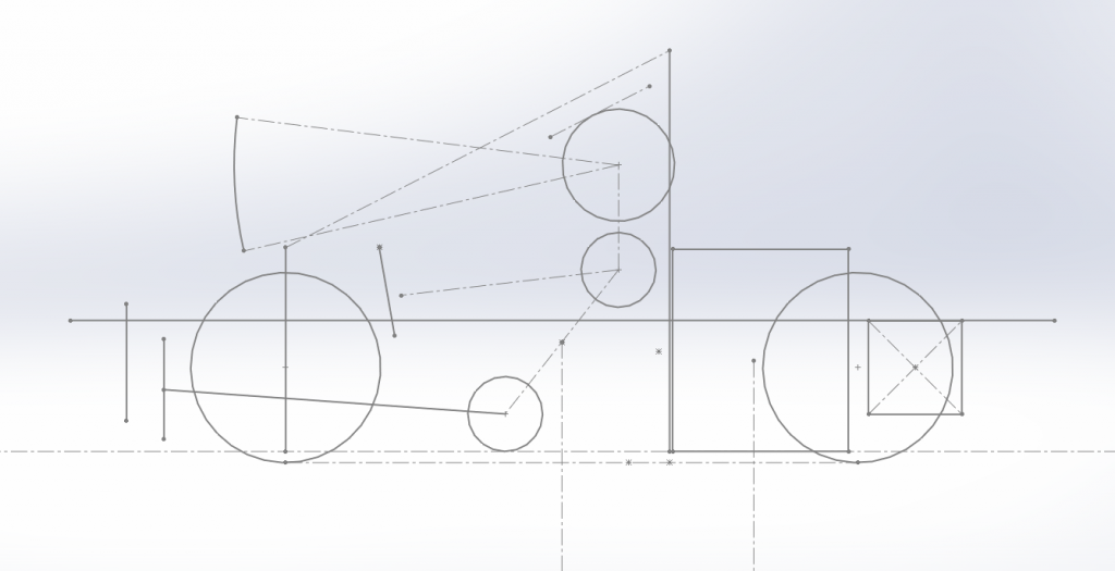
Anyway, onto sketches and a few ideas!
WB=1530mm
CG height (with current engine spec) = 297mm
CG height (with dry sump) ~ 250mm
F/R WD = 35/65
Ground clearance = 30mm
Basically the big square is the engine and the crossed square represents the size of our current diff sprocket, biggest circles are wheels, I've also included percy along with arms to get a feel of the steering reach required. Furthest forward point is the bulkhead/IA plate, next up is pedal face, etc (big cross line represents top of side impact structure).
Main assumptions are that the two largest masses drive the WD (driver + engine) I appreciate this will change substantially once the other parts are added in but that will probably move it forward 5% or so (I've also just realised the drivers CofG is probably slightly further forward given the leg position but I'll rectify that on MK2.
Slightly disappointed no one had anything to say about my thoughts on caster and hanging suspension hardpoints from the IA bulkhead
 |

|

 Reply With Quote